 In the last two months, I’ve become fascinated with clocks and automatons. My family never owned a mechanical clock, but I had an aunt with a musical cuckoo clock, and a grandfather clock that showed the phases of the moon. I wondered what made the pendulum keep swinging (was it magnets or batteries?), and what made the cuckoo bird sing.
I still don’t know what makes the cuckoo bird sing, but I now have a better idea of what makes the pendulum swing, thanks to Jeff Schierenbeck, the designer of the Ascent wooden gear clock, a kit I’ve been working on for the past few weeks.
I decided a few weeks ago to build a wooden gear clock because I wanted to understand the clock mechanism better. There are a number of websites that offer plans for wooden gear clocks, but as someone with absolutely no woodworkng experience (band practice generally interferes with taking shop class), and no tools, I needed something that was ready to build. I found four sites that offer such kits: Jeff’s wooden-gear-clocks.com, klockit.com. clockplans.com, and woodenclockworks.net.
Jeff’s website seemed to show the best design sense (the clockplans website is pretty awfull), and I hoped his good web design sense was an indicator of a superior product, so I ordered his simplest clock first. I’ve since ordered an Athena clock kit (because I want to understand the verge and foliot mechanism) and I’ll let you know how it compares to the Ascent in a later review.
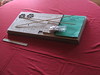
The Ascent kit arrived in a slim box which was about one foot by three feet. All the components are cleverly designed to fit within this package – the clock appears to be designed expressely for the mail order business.
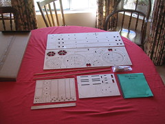
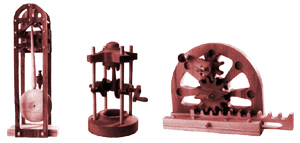
Here are the components spread out. Most of the parts are laser cut plywood. There are also some dowels, screws, nylon washers and string. The kit comes with a detailed and helpful 43 page instruction manual, that is *much* better than the terse instructions that come with IKEA furniture. Jeff is very careful to navigate you through most of the potential “gotchas” that will occur during the construction process. I started working on the clock about 2 and a half weeks ago, working mostly on weekends. All in all, I’ve probably spent about 20 hours on it thus far.
My son has been working on building a guitar, so we had some wood glue, sandpaper, clamps and a mallet, which is about all you need to build this. The parts are generally completely laser cut except for a small notch which holds them into the palette. You twist the part to remove it, and then sand the part. I was worried that some parts might split when I removed them, but I did not have any problems with this. At first, I very patiently sanded each piece, but a common problem seems to be letting your impatience get the best of you, and it is tempting to rush through the build. I suggest taking your time.
The instruction manual provides a stain guide for staining the parts three different shades. I left the ‘light’ pieces alone, and inexpertly stained the gears a medium color and the indicators a darker color, using some old cans of stain that the previous homeowner had left in the garage, and some Q-tips. My staining doesn’t look terrible, although I made the mistake of leaving a gear wet with stain to dry on a paper towel, which stuck to it. So the backside of my great wheel has an unintentional ‘antiquing’ effect. I have not yet attempted to apply varnish.
This was my first woodworking project, and the first time I used wood glue. Fortunately, the first thing you glue, according to the instructions, was not of major significance. Like most beginners, I used way too much glue at first. I got much better at applying glue as the project progressed.
In some cases, I found it difficult to keep pieces aligned when gluing them. My son helped me glue the large front and backframe pieces, but we ended up with one of them being slightly misaligned, because we weren’t observant enough when clamping them. This does not seem to have affected the working of the clock, however. I found that for the smaller pieces, it was easier if I held them in my hands while the glue set, rather than using a clamp.
The pendulum is probably one of the weaker aspects of this particular clock design. The pendulum shaft is 4 feet, and in order to fit it into the shipping package, it comes in two pieces which must be glued together. In my kit, one of those pieces was warped. I did a pretty good job of gluing them together straight, but there is still a pretty bad bow on one end of the shaft. I was also a bit too hasty in gluing the upper bracket on the pendulum shaft – this turns out to be a pretty important part of the mechanism, because the pendulum balances on two screws which are driven through this bracket. Mine came out a bit asymmetrical, and I’ve had to tweak it a few times.
The weight is a wooden box that is glued together. The instructions say to fill it with metal shot, or pennies. Since I don’t have a ready supply of metal shot, whatever that is, I chose pennies. The instructions say to use two pounds of metal shot. I weighed out two pounds of pennies, but found that they overflowed the space within the weight, so I ended up using about 1.8 pounds of pennies. This seems to be fine, however.
I waited a week before installing the gears on the arbors (the axle like dowels that they are mounted on). I was worried that I would screw this up, being such a big klutz, but it turned out to be pretty easy, and I think I did a pretty good job.
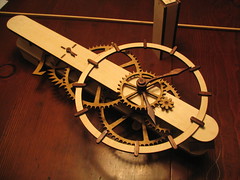
Installing the gears into the frame went very quickly, and suddenly, I had a working gear chain! This was a very surpirsing and satisfying part of the build experience for me. Having made some mistakes working up to this point, I was not all that confident that the gear chain would work, but it seemed to work flawlessly!
At this point, I was anxious to see the clock working, so I found a nail in the house where I could hang it, attach the weight and hang the pendlum. At first, I was only able to get it to run for a few seconds. Those first few ticks were very cool! But then it would stop. I then went thru a troubleshooting process that lasted a few days.
At first, I thought the problem was the warped pendulum. I corresponded with Jeff, who was quite happy to replace the shaft. But then I tried running the clock using my hand as a pendulum, and discovered that the escapement was still not working – it required far more than 2 pounds to get it to work. Looking back at the instrutions, I realized that I had skipped over an essential step: sanding the arbor dowels, to reduce friction in the gear train. I took the clock apart, sanded the shafts, and reassembled it. Now the gear train ran much more smoothly, and I was able to get the clock to run for 20 to 30 seconds.
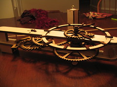
Finally, after tweaking the pendulum some more, and applying graphite to the escapement gear, my son got the clock to run continuously. As I write this, it has been running all evening, and I have set the hands to reflect local time for the first time. In the morning,
we’ll begin the process of adjusting the position of the pendulum bob, trying to make it more accurate.
The clock is now hanging in the living room, and it looks great. I wasn’t sure at first if my wife would want me to put it in such a public place, but she fell in love with it – it truly is a thing of beauty, and will be quite a conversation piece.
Obviously, I am very pleased with this kit, and will likely order Jeff’s second clock, the Serpentine, when I finish with the Athena. Building your own clock is truly the best means I can find for truly understanding how clocks and automatons work.
* * *
So how does this pendulum clock work? I’m trying to figure it out well enough that I can simulate it in a Flash movie (which I’ll add to the bestiary). My goal is to make a clock simulation that is robust enough that you can meddle with it by twiddling with the gears with the mouse. If I combine a clockwork based system with my spring phsyics system, I have the basis for making some silly and cool automatons in Flash or 3D – a kind of “kuckoo klock konstruction kit”. This is what I’ve figured out thus far:
The weight, which is attached to one of the arbors, supplies energy to the gear chain and makes all the gears want to spin. Without something to stop them, the gears would spin very quickly, and the hands would rotate very quickly until the weight hits the floor. This motion is arrested by the anchor escapement whose two arms (or “pallets”) hold the escapement gear in check. Mark Headrick has an excellent demonstration of an anchor escapement, and a good historical survey, on his website.
The anchor escapement, swings back and forth with the pendulum, which has a period of 2 seconds. Like all pendulums, it’s period is controlled entirely by its length, and not by its weight or the width of the arc it makes. You make the clock go faster or slower by moving the pendulum bob up or down on the shaft.
Each time the pendulum swings back and forth, the escapement allows one tooth of the escapement gear to advance. There are 30 teeth on this gear, so with one tooth advancing every 2 seconds, the entire gear has a period of 60 seconds (it takes a minute to rotate). The second hand is attached to this gear (and is separate from the main face of the clock).
The escapement gear (which is powered by the weight) also pushes the anchor, which in turn gives a little kick to the pendulum. That’s what keeps the pendulum swinging.
On the same arbor as the escapement gear is an 8-tooth gear, which is meshed with a 60-tooth gear on a second arbor.
This second arbor has a period of 60 seconds x (60/8) (60/8 is the ratio of the teeth of the two gears). So it spins once every 450 seconds. The second arbor also contains another 8-tooth gear which is meshed with a 64-tooth great wheel gear on the third arbor – the great wheel arbor.
So the great wheel arbor has a period of 450 seconds x (64/8) or 3600 seconds, or one hour. It rotates in one hour, and this is the arbor that the minute hand is attached to. This is also the arbor that the weight is attached to, although I’m not sure it matters all that much which arbor the weight is attached to – it supplies energy to the entire gear train.
There is a final arbor which is used to provide gearing for the hour-hand movement. On the great wheel arbor, there is a 10 tooth gear, which is meshed with a 30 tooth gear on this next arbor. This gear spins at a rate of 3600 seconds x (30/10) or 10800 seconds.
This arbor also has an 8-tooth gear which is meshed with a 32-tooth gear which is mounted on a pipe which makes it coincident with the great-wheel arbor (but unaffected by it’s spin). This pipe allows the hour hand to have the same mount position as minute hand, but to spin at a different rate. The period of the hour hand, which is also mounted on the pipe is 10800 seconds x (32/8) or 43200 seconds or 12 hours.
So the three magic numbers here are 60 -> 3600 -> 43200. There are other gears we could have used to get from 60 to 3600 or from 3600 to 43200 (providing a 60x and a 12x increase in the length of the period), but these are the choices of this particular clock designer. Different choices would effect the number of teeth in the gear, and the size of the gear. I’m guessing you don’t really want to use gears with fewer than 8 teeth, and you don’t want gears (especially wooden ones) with enormous numbers of teeth. This is why so many gears are needed. If you went straight from the escapement wheel to the great wheel (without the intervening arbor), the great wheel would need 1800 teeth. If we could live without a second hand, we could use fewer teeth on the escapement gear, and that might simplify the design.
So that’s how the Ascent clock works. More clock-related goodness to come in the coming weeks.